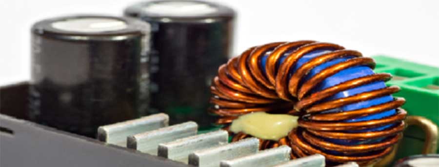
Understanding the inner workings of essential electronics such as transformers is crucial as the world advances in technological innovations. To fully appreciate the operation of toroidal transformers, it is imperative to grasp the fundamental operating principles of electrical transformers. An electrical transformer transports electrical energy from one circuit to another. This exchange occurs by generating an electromotive force (EMF) by a magnetic field, all while ensuring the electrical isolation of the two circuits. These invaluable devices are used in varying voltage applications – stepping it up or down without altering the frequency of the electric current.
Toroids
Toroidal transformers operate on the foundations of Faraday’s law of induction, a principle that emphasizes the direct relationship between a changing magnetic flux and the induced EMF. The magnetic flux is generated when magnetic field lines traverse through a conductor. Placing this conductor near a magnetic field with fluctuating amplitude initiates an electric current in the conductor – a phenomenon inherent to all electrical transformers, including toroids.
 The varying electric current, or alternating current (AC), is crucial to electromagnetic induction as it generates and collapses the magnetic field at a specified frequency. This frequency directly influences the induced electric current in a second conductor, which shares the same frequency as the primary electromagnet circuit. However, fluctuating amplitude isn’t the only method to induce a current. Another approach involves making the conductor “cut” through the magnetic field lines. This action prompts the generation of an electric current, a phenomenon typically observed in electrical generators.
A primary single-phase transformer serves as a simplified model for understanding toroidal transformers. This type of transformer contains two electrical coils – the primary and secondary windings. The power supply connects to the primary winding, while the secondary winding is where current is generated. Both of these windings are tightly encased within a closed-loop magnetic core.
The two windings communicate through a magnetic field despite not being electrically connected. By altering the number of coils relative to the other, the voltage in the secondary winding can be increased or decreased. Owing to its linear nature, the voltage generated in the secondary winding can be precisely predicted by determining the turns ratio (TR) – the ratio of the number of turns of the windings.
Transformers, including toroidal transformers, are often perceived as constant power devices, provided no losses exist. That means the power generated in the secondary winding matches the power supply in the primary winding. Consequently, the current must be reduced to escalate the voltage, and vice versa The efficiency of transformers usually ranges from 88 to 99%. When they occur, power losses can be attributed to core, copper, stray, and dielectric losses. Core losses arise from hysteresis or eddy currents, while copper loss is due to the electrical resistance of the copper windings. The stray loss stems from the leakage of the magnetic field influencing other conductive parts of the transformer. Dielectric loss occurs when the insulating materials and the transformer oil degrade.
The complex operation of toroidal transformers is grounded on fundamental physics principles. With an appreciation for these principles, we can better utilize these essential devices in our day-to-day lives. Furthermore, with custom coil winding, we can tailor these transformers to suit specific applications, pushing the boundaries of technological innovations.

