Toroids Explained: Design, Materials, Winding, and Mounting Considerations
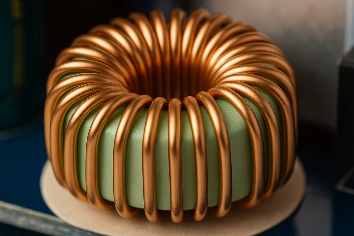
Toroids are ring-shaped magnetic components used in power supplies, inductors, chokes, audio systems, medical devices, and other electronic designs that require stable magnetic behavior. Their geometry confines magnetic flux within the core and limits stray fields, which provides a significant advantage over rectangular transformer cores. Although toroids appear simple, their performance depends on careful coordination of materials, winding methods, and mechanical decisions.
Understanding toroids is important because many issues that delay engineering projects are preventable. EMI failures, temperature issues, leakage inconsistencies, vibration concerns, and sourcing challenges often surface late in development, when changes are expensive and disruptive. These problems are not caused by toroids being unreliable. They occur when assumptions about materials or winding strategies do not align with the design's actual electrical or mechanical requirements.
A toroid consistently outperforms rectangular transformer cores when engineering and procurement teams select materials, winding methods, and mounting approaches that align with the system's operating conditions and performance expectations.
How a Toroid Works in Electrical Systems
A toroid is constructed by winding conductive wire around a circular magnetic core. When current flows through the winding, it creates a magnetic field that remains inside the core because the magnetic path is continuous. This confinement minimizes interference with surrounding components and reduces the need for additional shielding or mechanical separation.
Toroids can be built from ferrites, powdered iron, silicon steel, nickel iron alloys, and amorphous metals. The material determines permeability, saturation behavior, temperature stability, and core losses. Engineers must evaluate these variables early because material choice influences nearly every aspect of performance.
Inductance in a toroid depends on the number of turns, the permeability of the core, and the dimensions of the magnetic path. The induced voltage is described by e = L (di/dt), which means that inductance controls how strongly the component resists changes in current. The geometry of a toroid produces consistent inductance values and stable coupling, helping maintain performance across temperature and load variations.
Why Toroids Offer Clear Engineering and Procurement Benefits
Toroids reduce the risk of electromagnetic interference because the flux is confined within the core rather than leaking outward. This is valuable in systems where sensitive circuits share space with power components. It allows tighter PCB layouts and simplifies enclosure design.
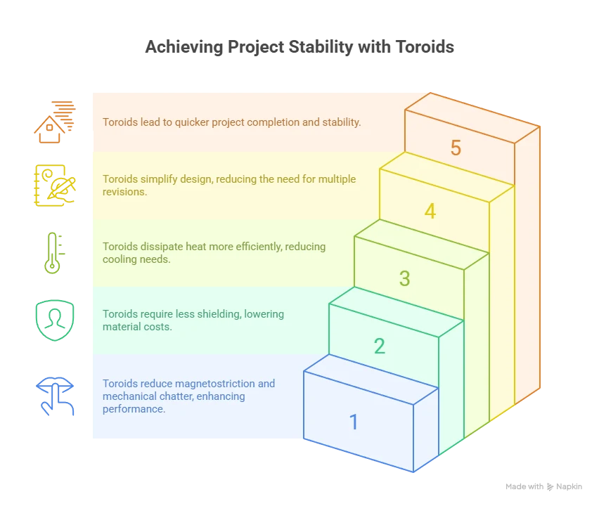
Efficiency is another important advantage. Toroids commonly operate between 90 and 98 percent efficiency because their magnetic path does not include gaps that dissipate energy. Lower losses reduce heat generation and improve reliability, thereby reducing thermal management requirements.
Noise and vibration are also lower in toroids. The continuous core structure limits magnetostriction and prevents the mechanical chatter seen in laminated cores. Industries such as audio, measurement, and medical instrumentation rely heavily on toroids for this reason.
From a procurement standpoint, these characteristics reduce the total cost of ownership. A toroid may cost more to manufacture, but it eliminates the need for heavy shielding, reduces thermal overhead, and lowers the number of design iterations required to meet compliance. Projects reach stability faster when a toroid is specified correctly.
Trade Offs and Performance Limits
Toroids are not ideal for every application. They require more labor to wind because each turn must pass through the core's center. This increases cost and lead time relative to EI transformers. Engineers must also design around high inrush current at startup. A toroid can draw a transient current that is several times its rated operating level. Without proper inrush control, this can cause tripping or component stress.
High-power designs above approximately 15 kilovolt-amperes are challenging to produce in toroidal form. The winding becomes difficult, and the cost rises sharply. EI or shell-type cores scale more efficiently and often provide better value for these applications.
Selecting Core Materials for Toroids
Core material determines how a toroid behaves under real operating conditions. Choosing the correct material prevents saturation, overheating, and instability.
- Silicon steel offers good low-frequency performance and durability. It is cost-effective but heavier than other materials.
- Ferrites are ideal for high-frequency operation and provide low eddy current losses. They saturate at lower flux levels and must be used within safe margins.
- Powdered iron supports stable inductance and strong saturation characteristics. It is commonly used in inductors and chokes.
- Nickel alloys and amorphous metals deliver extremely low losses and high energy efficiency but are more expensive.
- Moly permalloy powders and iron powder offer moderate permeability and stable performance in high-power inductors.
Engineers should match the material to the frequency, flux density, and temperature environment. Procurement should confirm material availability, alternate options, and long-term sourcing stability before finalizing a design.
Coil Winding Methods and Their Impact on Toroid Behavior
Winding strategy is one of the most influential aspects of a toroid design. The way the conductor is applied to the core determines the leakage inductance, the temperature profile, parasitic capacitance, and mechanical resilience.
- Full coverage winding wraps the conductor around the entire circumference. This minimizes leakage inductance and creates strong coupling. It is preferred for audio, measurement, and medical applications where magnetic precision matters.
- Sector winding intentionally leaves a portion of the core unwound. This increases leakage inductance and is useful in filtering stages or special power converter topologies.
- Single and multi-layer winding options affect physical size and capacitance. Multiple layers reduce external dimensions but increase parasitic effects. Interleaving layers can improve heat distribution and reduce capacitance.
- Mechanical tension and insulation quality determine whether the winding will hold its shape under vibration and temperature changes. Potting compounds or insulation wraps often improve long-term reliability.
Winding is not a cosmetic choice. It directly controls electrical behavior. When engineering and procurement align on winding details early, suppliers can deliver consistent magnetic performance across production runs.
Mounting Methods for Toroids
Mounting affects reliability, mechanical stability, and thermal performance. The chosen method must match the mechanical environment and expected stress levels of the system.
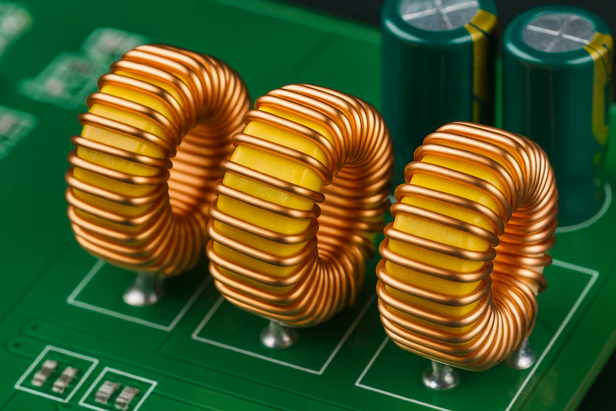
- Horizontal mounts place the toroid on its side. Leads pass through the PCB and are soldered underneath. This approach offers strong mechanical stability and is easy to assemble.
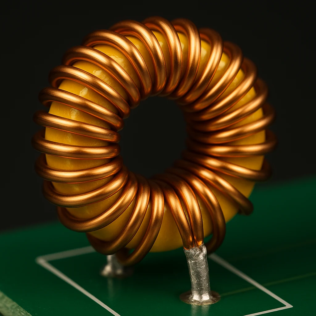
- Vertical mounts stand the toroid upright to save board space. They simplify cleaning under the component, but may be less resistant to mechanical shock.
- Surface mount headers support automated placement. They allow toroids to be placed directly onto solder pads, reducing labor and increasing manufacturing speed.
Mounting material and orientation affect cooling, vibration resistance, and long-term reliability.
Applications Where Toroids Provide Measurable Value
Toroids are widely used in linear and switch-mode power supplies, audio amplification, medical instruments, renewable energy systems, lighting controls, and precision test equipment. These applications rely on the quiet magnetic environment that toroids create. Reduced stray fields, lower noise, and strong efficiency help maintain system performance without forcing engineers to add shielding or redesign layouts.
Toroids are also valuable in energy storage and filtering because they provide stable inductance and predictable flux paths. When windings are applied correctly, a toroid can act as either an efficient transformer or a robust inductor, depending on the design.
However, toroids may not be appropriate for very high-power designs or multi-phase systems. EI or shell-type cores are typically more cost-effective and scalable in those applications.
Core Material Comparison for Toroid Design
Material Type |
Engineering Strengths |
Procurement Considerations |
Limitations |
Silicon Steel |
Strong low frequency performance |
Low cost and widely available |
Heavy and higher core losses |
Ferrite |
Excellent high frequency efficiency |
Lightweight and predictable supply |
Low saturation flux |
Powdered Iron |
Good saturation capability |
Moderate pricing |
Higher losses at high frequency |
Amorphous Metal |
Very low losses and high efficiency |
Higher cost with long term reliability benefits |
Requires specialized processing |
Moly Permalloy |
Good inductance stability |
Predictable sourcing |
Less efficient than ferrites |

Torelco: Your One Stop Shop for Toroids and Custom Coil Winding
Toroids deliver strong electromagnetic performance, high efficiency, and reliable behavior when their materials, winding methods, and mounting choices meet the demands of the application. Many design and sourcing challenges can be avoided when engineering and procurement coordinate these decisions early. This alignment prevents costly revisions, increases manufacturing predictability, and ensures each toroid performs consistently across every production batch. When used correctly, toroids become some of the most stable and efficient components in electronic systems.
FAQ About Toroids
What determines the inductance of a toroid? The inductance depends on the number of turns, the permeability of the material, and the geometry of the core. Temperature and magnetic saturation also influence stability.
Why do toroids produce less electromagnetic interference? The magnetic field is confined within the core's closed loop, minimizing stray fields and reducing coupling to nearby circuits.
When should a toroid not be used? Toroids are less practical for high-power or multi-phase systems because manufacturing becomes complex and expensive at large sizes.
How can inrush current be controlled in a toroid-based design? Engineers typically use soft-start circuits, NTC thermistors, or controlled startup strategies to limit inrush current to safe levels.
Does winding strategy affect leakage inductance? Yes. Full coverage winding keeps leakage low, while sector winding intentionally increases it for specialized designs.
Related Reading
- Custom Toroidal Transformers for Microgrids: Supporting Bidirectional Power Flow and Decentralized Renewable Integration
- What Factors Should You Consider When Choosing a Toroidal Inductor or Transformer for Your Application?
- How Does the Toroid Shape Reduce Electromagnetic Interference and Improve Efficiency in Transformers and Inductors?