

How to Diagnose Heat and Hum in an Installed Toroidal Transformer
When a toroidal transformer begins to hum or run hotter after installation, replacing the transformer is often the fastest action and the wrong first diagnosis. The same toroid now interacts with its mounting system and final load. Incoming supply conditions and the enclosed thermal environment add two more variables. A symptom appearing only in the finished assembly points to the whole operating system until measurements isolate one cause.
A disciplined diagnosis changes one condition at a time. The same discipline applies across toroids because every comparison holds all but one condition steady. First, document the symptom before loosening hardware or moving leads. Then separate mechanical amplification from electrical excitation. Compare no-load behavior with loaded behavior, followed by a separate comparison between open-bench and closed-enclosure operation.
When Should Testing Stop?
Heat and hum do not automatically prove a failed transformer, but troubleshooting must stop when the assembly shows damage or unstable behavior. Decide which measurements require energized access before removing a cover or exposing primary terminals. NFPA’s 2024 explanation of OSHA and NFPA 70E emphasizes electrical safety controls, even when a qualified person understands the equipment and the working voltage. That boundary matters because input-voltage, current, and waveform measurements expose personnel to mains energy. Qualified personnel should follow the employer’s approved electrical-safety procedure and instrument requirements for every energized test.
Stop energized testing and move to a de-energized inspection when any of these conditions appears:
- Smoke, arcing, or visible tracking.Disconnect the equipment under the approved emergency procedure.
- Insulation odor or discoloration.Treat softening, darkened material, and residue as evidence requiring inspection.
- Repeated protective-device operation. Do not keep replacing a fuse or resetting a breaker to continue the test.
- Uncontrolled temperature rise.Stop when temperature passes the approved limit or continues climbing without stabilizing.
- Damaged leads or exposed conductive parts.Correct the unsafe condition before collecting more operating data.
What Should You Record Before Changing Anything?
A useful diagnosis begins with the exact condition that produced the symptom. Record one operating state at a time, using the same measurement points during every comparison. Installed toroids should be judged against their approved electrical and thermal limits, not against a generic touch test. A repeatable record prevents a mounting change, load change, and supply change from becoming one inconclusive experiment.
Capture the baseline in six parts:
- Sound pattern.Describe a steady hum, intermittent buzz, or mechanical rattle and note the loudest location.
- Starting point.Record whether the symptom begins at energization, at no load, after load connects, or after the cover closes.
- Electrical state.Record primary connection, input voltage, output voltage, and measured secondary current.
- Thermal state.Record local ambient, transformer surface temperature, enclosure-air temperature, and elapsed operating time.
- Mechanical state.Photograph the mounting hardware, pad, surrounding clearances, and the panel nearest the loudest vibration.
- Repetition pattern.Note the branch circuit, time of day, nearby equipment, and duty cycle associated with the symptom.
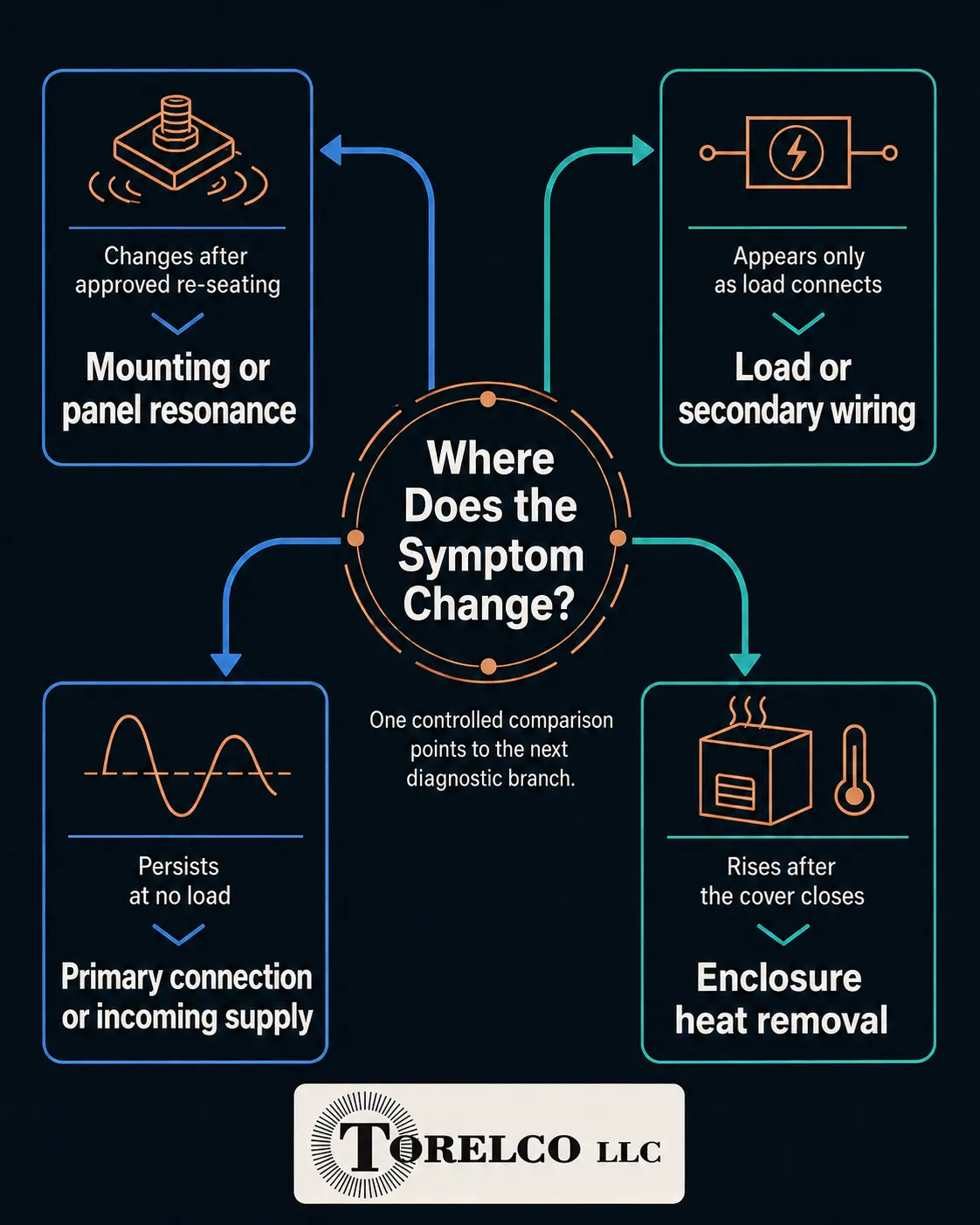
The first comparison should reproduce the original symptom without introducing a new variable. Match the input supply and load state. Keep the cover position and elapsed operating time consistent. Change one condition, then repeat the same measurements. The resulting pattern directs the next diagnostic branch.
| Observed pattern | First diagnostic branch | Evidence to collect |
| Hum changes after approved re-seating or when chassis contact is removed | Mounting transmission or panel resonance | Repeat the same no-load condition before and after the mounting correction. Record sound change and hardware condition. |
| Hum persists at no load and varies by branch circuit or time of day | Incoming voltage, waveform asymmetry, or a DC component | Record primary-terminal RMS voltage, no-load primary current, waveform evidence, branch, and time. |
| Heat or hum begins as downstream circuits connect | Connected demand, duty cycle, secondary configuration, or phasing | Record output voltage and current for each load state. Compare wiring with the released diagram. |
| Bench behavior is acceptable, but temperature rises after the cover closes | Local ambient temperature or inadequate heat removal | Compare open and closed conditions at the same load. Log local ambient, surface temperature, and elapsed time. |
| Output voltage is abnormal while no-load primary current is elevated | Primary connection, applied voltage, winding configuration, or transformer condition | Verify the nameplate, primary lead selection, supply at the transformer terminals, and all no-load secondary voltages. |
Does the Hum Follow the Mounting or the Electrical Condition?
A hum present at no load does not automatically indicate damaged windings. An energized magnetic core already produces small mechanical movement, and the surrounding structure determines how much sound reaches the listener. A 2021 peer-reviewed investigation of transformer-core vibration linked no-load core vibration to magnetostriction in the electrical steel. The researchers also found a significant relationship between core vibration and noise, with modal behavior affecting intensity. A rigid panel or unintended contact path in the installed assembly therefore deserves comparison before the transformer is labeled defective. The diagnostic question is whether the sound changes while electrical conditions remain the same.
Document the current mount before making any change. De-energize the equipment, then compare the pad and clamp with the approved assembly. Check the washer and center hardware during the same review. Remove any unintended contact with the cover or any nearby structure, and reassemble only to the documented requirements. Re-energize under the same no-load condition and record whether the sound level or character changed.
Does Heat or Hum Increase with Load?
A symptom that appears only as downstream circuits connect narrows the diagnosis toward load demand, secondary configuration, or heat removal. Compare measured secondary current with the rating for the selected connection and expected duty cycle. A 2020 study of maximum temperature in toroidal transformers developed a thermal model based on transformer geometry and physical properties, and then examined the influence of electric current and ambient temperature. Experimental tests were used to validate the model. The findings support treating load current and local ambient as separate measurements rather than calling every hot toroid overloaded. Both values are needed before temperature rise has diagnostic meaning.
Begin with the qualified no-load baseline, then add one downstream circuit at a time. Record secondary voltage, secondary current, and temperature at fixed intervals for each state. Verify every series or parallel connection against the released diagram, as incorrect phasing can produce abnormal current or output. If the symptom begins when one load connects, inspect that branch and its wiring before condemning the transformer.
Does the Symptom Persist at No Load?
Hum or elevated primary current at no load shifts attention toward the applied excitation and primary connection. Measure supply voltage at the transformer terminals during the same period when the symptom occurs. A 2024 Electronics study of transformer saturation included laboratory tests on a 200 VA single-phase toroidal transformer under mixed AC and DC excitation. The mixed excitation produced a significantly higher primary current than the normal no-load case, while the secondary voltage remained unaffected. That result shows why an apparently normal output-voltage reading does not rule out a supply condition pushing the core toward saturation. Higher-than-rated RMS voltage and waveform asymmetry therefore belong in the no-load investigation.
A true-RMS reading establishes voltage magnitude but does not describe the entire waveform. When sound varies by branch circuit, time of day, or nearby machinery operation, capture the waveform under the approved test method or compare operation on a verified supply. Record no-load primary current during both a quiet period and the symptomatic period. A replacement transformer or added line device should not serve as proof of cause without those measurements.
Bring Torelco Measurements, Not Just a Symptom
An installed toroidal transformer should not be judged from heat or hum alone. Mounting and no-load excitation identify the first diagnostic branch. Load response and enclosure temperature complete the separation. Document safe, repeatable measurements before swapping parts, then send Torelco the released wiring information and nameplate data. Include the test record and installation photos. Our team will review whether the evidence indicates an assembly correction or a part replacement. Repair and custom coil winding remain separate paths when the transformer condition or application requirements have changed.
Related Reading
- Where Are Toroidal Transformers Used Today?
- The Engineering Gap: Why Your Custom Toroidal RFQ Dictates Success
- Repairing Old, Broken Toroids: The Engineering Protocol
- Built to Fit, Built to Last: How Custom Toroids Solve Sourcing Problems Before They Start
- Designing with Purpose: Why Engineers Choose Custom Toroids for Precision Performance