

How Does Sector Winding Reduce Parasitic Capacitance in Toroids?
The Parasitic Capacitance Bottleneck in High-Frequency Inductors
In modern wide-bandgap power conversion systems utilizing silicon carbide (SiC) and gallium nitride (GaN) switching devices, switching frequencies regularly exceed 500 kHz to 2 MHz. At these extreme di/dt and dv/dt transition speeds, high-frequency common-mode noise threatens electromagnetic compliance across industrial drives, electric vehicle powertrains, and renewable energy inverters. When magnetics design engineers evaluate a custom toroid choke for EMI filtering, they quickly discover that nominal low-frequency inductance tells only half the story. Parasitic inter-turn capacitance (Cp) is the real performance limiter; it causes the choke to lose inductive impedance and resonate at higher frequencies.
Above an inductor's self-resonant frequency (SRF), capacitive reactance dominates inductive reactance. The component effectively flips from being a high-impedance noise barrier into a low-impedance bypass capacitor, allowing destructive high-frequency noise spikes to pass freely into downstream electronics. To conquer this frequency ceiling, magnetics engineers deploy sector winding—an advanced precision winding architecture that drastically cuts parasitic capacitance.
The Physics of Self-Resonant Frequency and Inter-Turn Coupling
Every wire-wound inductor is inherently a distributed LC network. The copper wire wraps around the core, forming inductance (L), while the dielectric insulation between adjacent wire turns creates distributed electrostatic capacitance (Cp). The classic resonance equation dictates the component's self-resonant frequency: SRF = 1 / (2π √(L · Cp).
In a standard continuous single-layer winding, wire turns progress uniformly around the core's full 360-degree circumference. While this appears clean and symmetrical, it creates an acute capacitive vulnerability. The first turn (connected to the input terminal) and the final turn (connected to the output terminal) end up sitting physically adjacent to one another across the core's closing gap.
Because the entire alternating voltage drop (ΔV) across the inductor appears across this tiny physical separation, intense electrostatic coupling occurs. Under the fundamental capacitance formula C = ε · A / d, the close proximity (small d) and high voltage gradient generate substantial stray capacitance. This high end-to-end capacitance bridges the inductor, pulling its SRF down into the low megahertz realm—precisely where severe GaN switching harmonics radiate.
Sector Winding Mechanics: Splitting Capacitance in Series
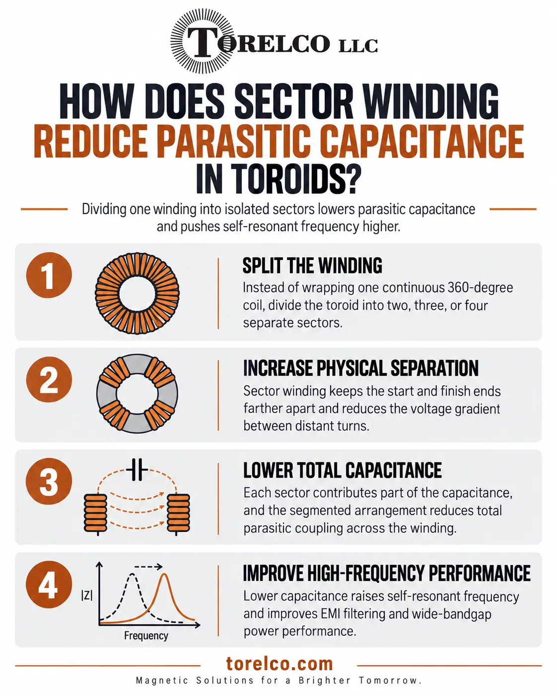
Sector winding (often termed progressive bank winding or sectional winding) eliminates this end-to-end capacitive bridge by physically segmenting the winding around the core into discrete angular zones separated by physical barrier gaps.
- Angular Core Segmentation: Rather than winding wire in a single continuous sweep across the core, the toroidal circumference is divided into distinct physical sectors (typically two, three, or four sectors) separated by non-conductive mechanical spacers or unwound core arcs.
- Reduced Inter-Turn Voltage Gradients: Within each sector, wire turns are wound progressively in tight localized banks. Because only a fraction of the total turns exist in each sector, the voltage differential between adjacent turns is reduced dramatically.
- Physical End-to-End Isolation: The input lead enters at the start of the first sector, while the output lead exits from the far side of the final sector. The input and output terminals are physically separated by up to 180 degrees of open core space, completely eliminating the high-voltage capacitive bridge.
From a circuit analysis standpoint, dividing a winding into N isolated sectors places the parasitic capacitances of each sector in electrical series: 1/Cp(total) = 1/Cp1 + 1/Cp2 + ... + 1/CpN. For a two-sector winding, effective parasitic capacitance is cut by more than half; for a three-sector design, it drops by up to 70%. By reducing Cp, the self-resonant frequency shifts outward by an octave or more, maintaining high inductive attenuation well into the 30 MHz to 100 MHz spectrum.
Comparing Toroidal Winding Techniques and Electrical Performance
Winding Architecture | Self-Resonant Frequency (SRF) | Parasitic Capacitance (Cp) | Dielectric Creepage / Clearance | Controlled Leakage Inductance | Manufacturing Complexity |
Standard Continuous Single-Layer | Moderate (typically 5 to 15 MHz) | High (end-to-end capacitive bridge) | Poor (< 2 mm lead separation) | Very Low (< 0.5% of nominal L) | Low; automated high-speed winding |
Standard Continuous Multi-Layer | Low (typically 1 to 5 MHz) | Very High (inter-layer capacitance) | Poor (adjacent input/output wires) | Extremely Low | Low to Moderate |
Two-Sector Winding (180° Spacing) | High (typically 20 to 50 MHz) | Low (capacitances in series) | Excellent (> 10 mm physical barrier) | Moderate (1.0% to 2.5% of nominal L) | Moderate; requires multi-pass tooling |
Three-Sector Winding (120° Spacing) | Very High (typically 40 to 80+ MHz) | Extremely Low (tri-series reduction) | Superior (isolated sector barriers) | Higher (2.5% to 4.0% of nominal L) | High; precision indexed winding |
High-Voltage Safety and Controlled Leakage Inductance
Beyond broadband EMI attenuation, sector winding delivers two substantial secondary engineering advantages that are highly prized in power electronics packaging.
First, it provides outstanding dielectric creepage and clearance. Under international safety standards such as IEC 62368-1 and UL 60950, mains-connected components must maintain strict physical separation distances between isolated winding circuits. By confining separate phases or lines to isolated 180-degree sectors, toroidal common-mode chokes achieve dielectric isolation ratings exceeding 3,000 to 4,000 VAC without requiring costly potting cups or thick insulating sleeves.
Second, sector winding introduces a predictable, controlled degree of leakage inductance. In conventional inductors, leakage flux is viewed as a parasitic loss. However, in switch-mode power topologies, designers can intentionally harness this controlled leakage inductance to act as an integrated differential-mode filter. A single two-sector toroidal choke can simultaneously filter high-frequency common-mode noise and low-frequency differential-mode ripple, eliminating the need for a separate differential inductor on the PCB.
Impedance Characterization and Vector Network Analyzer Verification
Validating parasitic capacitance reduction requires laboratory impedance characterization across broad frequency sweeps. Engineers evaluate prototype sector chokes using precision impedance analyzers or vector network analyzers (such as the Keysight E4990A) spanning 100 kHz to 120 MHz.
By monitoring the phase angle transition—where the component shifts from a purely inductive +90-degree phase through resonance (0 degrees) into a capacitive -90-degree phase—test engineers pinpoint the exact self-resonant frequency. Comparing standard continuous windings with precision sector windings consistently shows that sectoring pushes the 0-degree crossover point out by 2.5x to 4x, maintaining crucial insertion-loss margins across severe EMI test bands.
Consultative Magnetics Engineering for Wide-Bandgap Applications
Designing high-performance magnetic components for SiC and GaN power converters requires looking beyond basic Henry ratings. Mastering high-frequency impedance means optimizing winding geometry, controlling inter-turn capacitance, and pushing self-resonant frequencies well above switching-noise harmonics.
By collaborating directly with specialized custom magnetics manufacturers, engineering teams can tailor sector winding geometries, core materials, and wire selections to their exact circuit parameters. Sourcing precision-wound sector toroids provides the high-frequency attenuation and robust dielectric isolation needed to ensure full electromagnetic compliance across next-generation power systems.