

How to Prevent Toroid Coil Fit Problems before Winding Begins

A toroid core that drops cleanly into a housing does not answer the fit question. Copper builds outward and upward as turns accumulate. Every layer also narrows the center opening. Insulation and lead transitions create local high points, so the finished coil becomes a different mechanical part from the bare core.
Fit problems become expensive after winding because most corrections affect more than shape. Reducing the winding build changes the electrical design. Moving a lead exit changes the assembly route, while removing insulation is not an acceptable clearance fix. The release package therefore needs to define the finished envelope before the first turn is wound.
Start With the Finished Coil Envelope
Bare core dimensions describe the starting geometry, not the part entering the customer’s assembly. The finished envelope grows with conductor diameter and layer count, while the usable opening moves in the opposite direction. Riegler and Muetze’s 2023 IEEE study modeled the physical winding process of a toroidal inductor rather than relying on a general fill factor. Their model reduced the usable inner radius by one wire diameter for each new layer and increased finished outer diameter and height by two wire diameters per layer. Production details change the exact build, but the geometric relationship stays the same. Core OD, core ID, and core height, therefore, do not establish the final fit on their own.
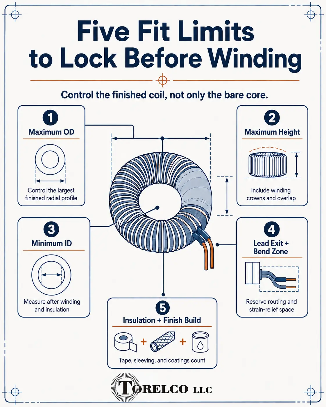
A mechanical requirement should place limits on the wound part. Use maximum values where the assembly surrounds the coil, such as outer diameter and height. Use a minimum value where hardware or another feature passes through the center. If clearance varies around the circumference, define a restricted sector rather than forcing an unnecessarily tight limit across the entire coil.
Let the Tightest Assembly Interface Set the Limits
The assembly should determine which dimensions receive firm limits. A generous enclosure does not help when one bracket passes close to the winding crown or a cover sits low over a tape overlap. Winding variables also influence one another, so a late request for a smaller profile is not always a simple shop-floor adjustment. A 2024 peer-reviewed study on loss-optimized magnetic devices linked conductor diameter and turn count with the number of winding layers. Spacing and winding arrangement also formed part of a model that constrained the winding cross-section to the maximum available window area. Those relationships support setting the assembly boundary before winding details are finalized. A firm boundary gives Torelco a clear basis for evaluating against the electrical requirements.
Four finished-part dimensions usually carry most of the fit decision. Each one controls a different interference risk. Start with these four controls, then add an application-specific limit only when a real interface requires one. Every limit needs a defined measurement reference.
- Maximum finished outer diameter. Control the largest radial profile across the completed coil, including localized winding or tape build.
- Maximum finished height.Measure from a defined mounting face and include the highest winding crown, overlap, or lead transition.
- Minimum finished center opening.Set the smallest acceptable passage after the complete winding and insulation system is applied.
- Restricted local profile. Mark the arc where a board, bracket, fastener, or cover requires tighter clearance than the rest of the circumference.
Protect the Center Opening Through the Full Build
The center opening serves as both available winding space and an assembly interface. Turns accumulate on the inside radius faster than visual estimates often suggest because the inner circumference is shorter than the outer circumference. Tape and other insulating layers further reduce the remaining passage. A minimum finished ID should therefore describe the opening after each specified layer, rather than an intermediate winding condition.
The required passage also needs a purpose. A center stud needs room for the stud and practical installation clearance. A wire bundle needs space for the largest item passing through, which might be a connector rather than the cable body. Tool access matters when a nut, washer, or fastener must be reached through the opening after the toroid is seated.
Before setting the minimum finished ID, answer three questions:
- What passes through the opening?Identify the largest hardware, connector, tool, or routed component involved in assembly.
- When does the pass-through occur?Distinguish the installation path from the final seated condition.
- Which finished layers count?Include tape, sleeving, coating, and any inner-radius overlap required by the released construction.
Treat Lead Exits as Part of the Mechanical Fit
A coil body might clear every nearby surface while the leads collide with the assembly. Lead fit depends on where each conductor exits the winding and how much clearance there is for the first bend. A bend forced against the coil body also transfers assembly stress into the transition point. NASA’s 2022 cable and harness workmanship standard requires defined bend radii for installed wiring and stress relief for wires exiting connectors. The standard addresses aerospace cable and harness work, but the mechanical principle applies directly to a toroid lead transition. Lead direction, bend space, and restraint need to be defined before the winding is fixed in place.
A production drawing should control the lead path with specific, measurable callouts:
- Exit origin.Locate the point where the lead leaves the wound body.
- Clock position. Reference the exit to a defined face, centerline, orientation mark, or mounting feature.
- Free and stripped length. Separate usable lead length from the portion consumed by routing around the coil.
- First-bend zone.Reserve enough space for the intended bend without forcing the conductor against an edge or surface.
- Grouping and identification.Define which leads remain paired, separated, twisted, sleeved, or color-marked.
Multiple windings require more than a lead count. Two exits placed at the same clock position might compete for a single narrow route, even when both exits are adequate in length. Taps also need enough separation for clear identification and termination. A marked assembly view often resolves these relationships faster than a note describing the preferred side in words.
Include Insulation and Finish Thickness in the Envelope
Insulation occupies real space and sometimes creates the highest point on the finished coil. Voltage and application shape the required system. Construction details and applicable safety requirements add further constraints. A 2022 IEEE Transactions on Power Delivery paper used three-dimensional toroidal transformer geometry to optimize insulation thickness and an electrostatic shield under fast-front excitation. The medium-voltage application differs from many commercial coils, but the analysis makes the mechanical point clear. Insulation thickness is a design variable tied to the winding geometry, not a finish to add after envelope limits are set. The fit review needs to include all required barriers before approving the maximum OD, height, and minimum ID.
A single blanket allowance rarely describes the actual build well. A full wrap changes the entire circumference, while an overlap creates a local increase. Lead sleeves affect the transition zone rather than the coil body. Varnish or coating might add little nominal thickness yet still matter where assembly clearance is narrow, so the released requirement should name the included finish and the location of each controlled measurement.
Control the Interfaces the Nominal Envelope Misses
Overall OD and height do not capture all interference conditions. Two coils with the same maximum dimensions might fit differently when their high points occur in different locations. Orientation must therefore use a stable reference shared by the drawing and the physical part. ISO 5459:2024 defines the terminology and methodology for datum systems in technical product documentation. Applying that discipline to a toroid means locating lead exits and restricted zones from a defined mounting face, axis, or orientation mark. Phrases such as “leads on the left” should not govern production, as the viewing direction remains ambiguous.
| Assembly interface | Requirement to control | Failure the requirement prevents |
| Center post, stud, or boss | Minimum finished center opening, measured after all winding and insulation at the tightest point | Binding during placement, damaged insulation, blocked hardware, or a coil that never seats fully |
| PCB edge or tall component | Local radial and vertical clearance in the installed orientation, referenced to the board | Pressure on winding crowns, displaced leads, damaged solder joints, or contact with nearby components |
| Bracket, clamp, or mounting pad | Approved contact zone, compression limit, fastener sweep, and tool access | Uneven seating, pinched leads, damaged finish, or blocked fastener access during assembly |
| Enclosure wall or cover | Maximum finished height and OD, including local tape overlaps and winding crowns | Cover interference, forced placement, abrasion, or loss of the designed air gap |
| Lead slot, connector, or harness path | Exit clock position, first-bend zone, usable free length, and finished sleeve diameter | Sharp bends, excess slack, strained terminations, crossed leads, or missed connector reach |
| Installation path and tooling | Clearance through the narrowest point before the coil reaches its final seat, including tool access | A finished coil that fits at rest but cannot reach or be secured in position |
Local requirements often protect fit with less design disruption than tighter overall tolerances. A restricted arc preserves room where the assembly needs clearance while allowing a practical winding profile elsewhere. The same approach works for a lead sweep zone or a no-contact area near a PCB. The drawing should show where the limit applies, which reference controls the location, and whether the value is a maximum profile or a minimum clearance.
Set the Fit Before the First Turn Is Wound
A finished toroid should enter production with mechanical limits as clear as the electrical requirements. Core dimensions alone do not provide that control. Define the wound envelope and protect the center opening. Locate every lead exit, then show the surrounding interfaces responsible for tight clearance. Send Torelco the assembly drawing and finished dimensional limits before winding begins. Include the approved lead layout and installation context so our team can review manufacturability and fit against the real application.