

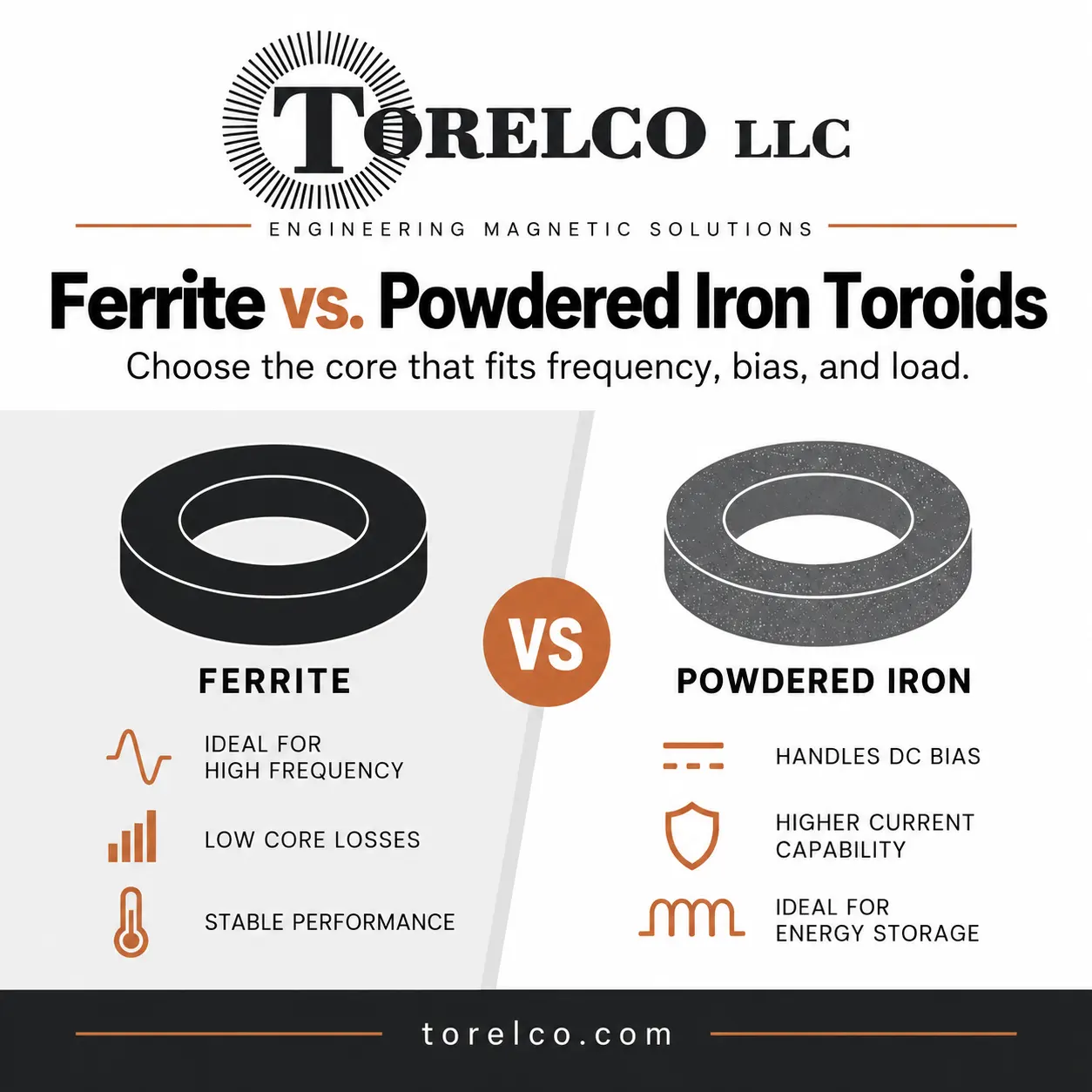
Ferrite vs. Powdered Iron Toroids: Which Should You Choose?
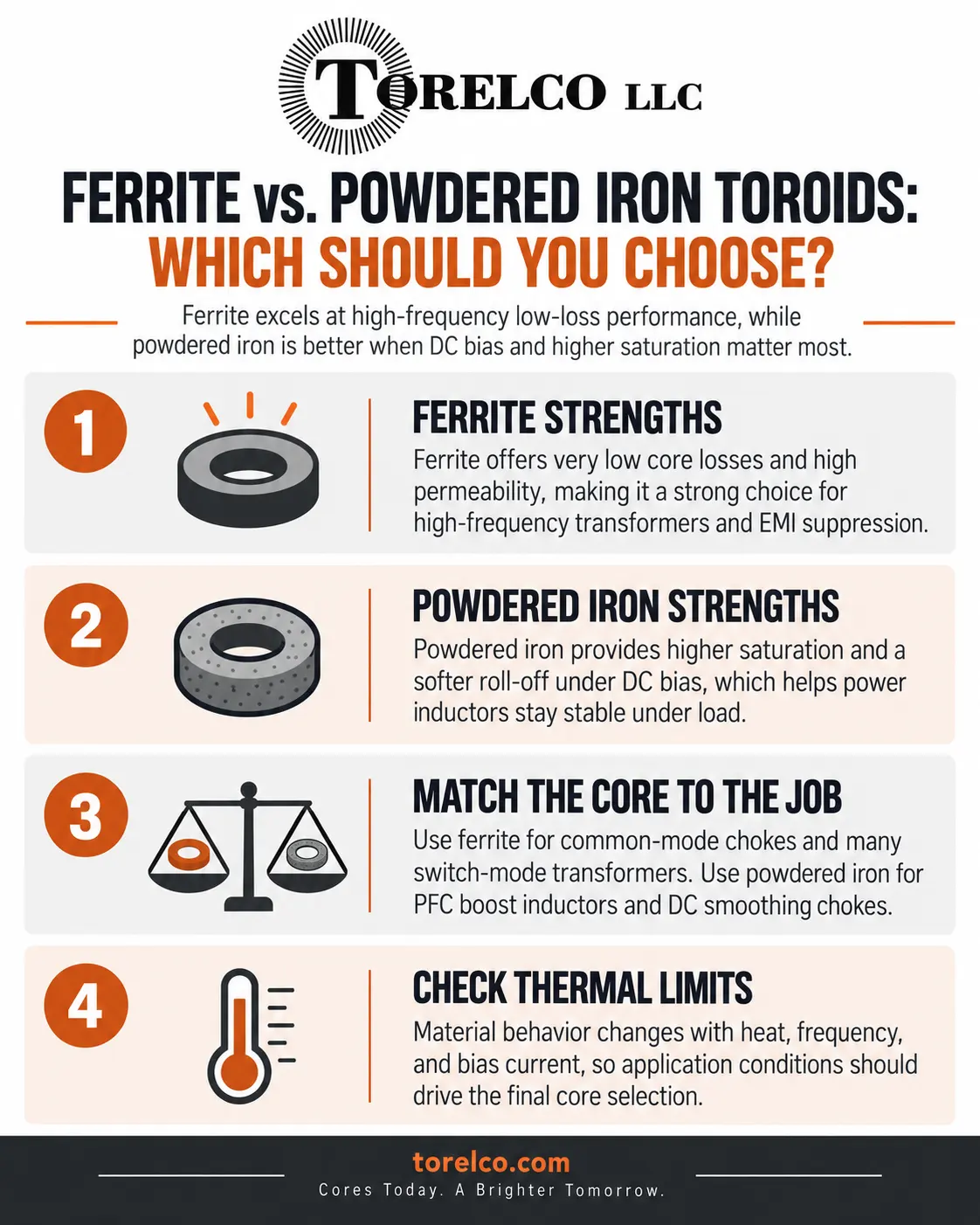
The Core Material Dilemma in High-Frequency Magnetics
In modern switch-mode power supplies (SMPS), solar micro-inverters, RF broadcast amplifiers, and electric vehicle onboard chargers, selecting the right magnetic core material is the most critical decision in inductor and transformer design. When electrical engineers evaluate toroids for filtering and energy storage, they invariably confront the classic engineering crossroads: ferrite versus powdered iron. Choosing the wrong core material can trigger disastrous design consequences, from catastrophic thermal runaway caused by core saturation to excessive eddy current losses that destroy operating efficiency.
While both materials can be pressed and sintered into identical doughnut-shaped toroidal cores, their underlying solid-state physics, magnetic permeability, saturation characteristics, and frequency responses differ fundamentally. Navigating these trade-offs requires matching the core's intrinsic magnetic behavior to the exact electrical demands of your circuit topology.
Ferrite Toroids: Ultra-High Permeability and Low Core Losses
Ferrites are dense ceramic magnetic materials formed by sintering iron oxide (Fe2O3) blended with metallic oxides such as manganese-zinc (MnZn) or nickel-zinc (NiZn). The resulting crystalline ceramic possesses an exceptionally high electrical volume resistivity—typically thousands to millions of ohm-centimeters.
- Manganese-Zinc (MnZn) Ferrites: Engineered for power frequencies ranging from 10 kHz to 2 MHz. MnZn cores feature high initial permeability (typically µi from 2,000 to 15,000), making them ideal for broadband common-mode EMI chokes, telecommunications pulse transformers, and compact resonant inductors that need maximum inductance with minimal wire turns.
- Nickel-Zinc (NiZn) Ferrites: Engineered for high-frequency RF applications spanning 1 MHz to 500 MHz. NiZn materials have lower initial permeability (µi from 15 to 1,500) but extraordinary electrical resistivity (>10^5 Ω-cm), virtually eliminating eddy-current losses in high-frequency RF baluns, antenna matching networks, and broadband RF filters.
However, ferrite cores have a primary vulnerability: low saturation flux density (Bsat), typically capping out between 0.35 and 0.45 Tesla (3,500 to 4,500 Gauss). Furthermore, ferrites exhibit a 'brick wall' saturation profile: as DC bias current increases, the core maintains inductance steadily until reaching saturation, where permeability plunges precipitously to near zero. In high-current DC energy storage inductors, this sharp drop can cause instantaneous current spikes that destroy switching MOSFETs.
Powdered Iron Toroids: High Saturation and Distributed Air Gaps
Powdered iron cores take an entirely different metallurgical approach. Rather than sintering a continuous ceramic oxide, manufacturers blend microscopic, highly pure iron particles coated with an electrically insulating organic binder or resin, pressing the mixture into a toroidal die under immense mechanical pressure (over 50 tons per square inch).
The microscopic resin insulation around each metallic iron grain acts as an intrinsic, evenly distributed air gap throughout the core's entire volume. This physical architecture provides two immense operational benefits.
1. High Saturation Flux Density (1.2 to 1.5 Tesla): Because the core contains pure metallic iron rather than ceramic oxides, powdered iron can absorb three to four times more magnetic flux than ferrite before saturating.
2. Soft, Gradual Saturation Curve: As heavy DC bias current ramps up, the distributed air gap causes permeability to decline gradually and predictably rather than collapsing off a cliff. This 'soft' roll-off ensures power supply inductors maintain filtering control even during severe load transient surges.
Technical Comparison: Ferrite vs. Powdered Iron vs. Sendust
Magnetic Characteristic | MnZn Ferrite Core | NiZn Ferrite Core | Standard Powdered Iron | Sendust / Kool Mμ Alloy |
Initial Permeability (µi) | 2,000 to 15,000 (Very High) | 15 to 1,500 (Moderate) | 10 to 100 (Low) | 60 to 125 (Moderate) |
Saturation Flux (Bsat) | 0.35 to 0.45 Tesla | 0.25 to 0.35 Tesla | 1.20 to 1.50 Tesla | 1.00 to 1.05 Tesla |
DC Bias Saturation Curve | Sharp; sudden collapse | Sharp; sudden collapse | Soft; gradual roll-off | Soft; gradual roll-off |
Core Eddy Current Losses | Extremely low at <2 MHz | Near-zero up to 500 MHz | High above 100 kHz | Low to moderate up to 500 kHz |
Typical Operating Frequency | 10 kHz to 2 MHz | 1 MHz to 500 MHz | DC to 100 kHz | 10 kHz to 500 kHz |
Primary Circuit Roles | Common-mode EMI chokes, pulse xfmrs | RF baluns, VHF/UHF filters | PFC chokes, DC output chokes | High-efficiency buck/boost inductors |
Thermal Stability, Core Losses, and Aging Phenomena
Thermal management is another critical differentiator between these material families. Ferrite materials are completely inorganic ceramics that do not age; their magnetic properties remain stable across decades of operation. However, ferrites possess relatively low Curie temperatures (Tc), typically between 120°C and 220°C. As operating temperatures approach the Curie threshold, saturation flux density and permeability degrade rapidly.
Powdered iron cores, in contrast, feature a high Curie temperature well above 700°C for the iron particles themselves. However, because powdered iron relies on organic chemical resins to insulate the particles, prolonged operation above 125°C can cause thermal aging. Over thousands of hours of severe thermal stress, the organic binder can oxidize and degrade, increasing eddy-current losses and self-heating. For extreme-temperature power applications, advanced metal alloy powder cores like Sendust (Fe-Si-Al) or MPP (molypermalloy) utilize inorganic binders to eliminate thermal aging entirely.
Application Matrix: Matching the Core to the Circuit Function
Selecting the optimal core material comes down to the primary electrical role within your power architecture.
- Common-Mode EMI Suppression Chokes: Choose high-permeability MnZn Ferrite. Common-mode lines carry minimal net DC flux, letting designers use high permeability to achieve high impedance with minimal turns.
- Power Factor Correction (PFC) Boost Inductors: Choose Powdered Iron or Sendust. These circuits subject the core to large DC bias currents overlaid with high-frequency switching ripple, requiring high Bsat and soft saturation to prevent core saturation.
- High-Frequency Switch-Mode Transformers: Choose Ferrite. Because power transformers transfer energy rather than store it, low hysteresis and eddy-current losses at 100 kHz to 1 MHz are essential for high efficiency.
- DC Output Smoothing Filter Chokes: Choose Powdered Iron. The continuous DC current would drive an ungapped ferrite core into instant saturation, whereas powdered iron handles continuous current with ease.
Consultative Magnetic Component Engineering
Navigating the subtle solid-state physics of magnetic core materials requires balancing electrical frequency, ambient temperature, DC bias currents, and thermal dissipation budgets. A core material that excels in a benign laboratory prototype can easily fail under severe environmental field conditions if permeability roll-off is miscalculated.
Partnering with custom magnetics engineering specialists ensures that every inductor and transformer is optimized from core alloy selection down to wire gauge and winding pattern. Sourcing precision-wound components guarantees robust power conversion, optimal thermal margins, and unyielding reliability across complex power electronics platforms.