

Why Do Toroidal Transformers Emit Far Less EMI Than EI Cores?
The Physics of Magnetic Flux Leakage in Power Supplies
In precision medical diagnostics, high-end audio preamplifiers, laser instrumentation, and sensitive aerospace sensor payloads, managing electromagnetic interference (EMI) is a relentless design challenge. When electrical engineers evaluate magnetic power components, specifying a toroid transformer over a conventional laminated E-I core often means the difference between pristine signal fidelity and pervasive 60 Hz background hum. Traditional laminated transformers act like radiant electromagnetic emitters inside compact electronics enclosures, coupling stray magnetic fields directly into high-gain analog traces, high-resolution analog-to-digital converters, and sensitive input stages.
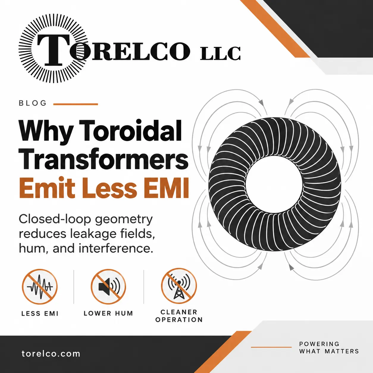
The fundamental difference between these two transformer topologies does not lie in magical shielding paints or exotic outer packaging; it stems directly from magnetic circuit geometry. While laminated E-I transformers inevitably leak stray magnetic flux at internal mechanical air gaps, a toroidal transformer provides a continuous, symmetrical, closed-loop magnetic circuit that traps magnetic flux within the core itself.
Continuous Core Geometry: Eliminating the Air Gap Source
To understand why toroidal cores emit so little EMI, one must first analyze why conventional EI transformers radiate so much. An EI transformer is constructed by stacking stamped silicon steel sheets shaped like the letters 'E' and 'I' through the center of a pre-wound bobbin. Regardless of how tightly these steel laminations are clamped or interleaved during factory assembly, a physical mechanical seam—an air gap—remains wherever the E and I plates meet.
Air possesses a magnetic permeability thousands of times lower than silicon steel. When alternating magnetic flux travels through the transformer core and encounters these microscopic air gaps, it faces high magnetic reluctance. The flux literally spills outside the steel boundaries, creating fringing flux fields that balloon outward into the surrounding enclosure as an omnidirectional dipole radiator. In contrast, a toroidal core is manufactured by tightly coiling a single, continuous ribbon of grain-oriented silicon steel into an unbroken ring.
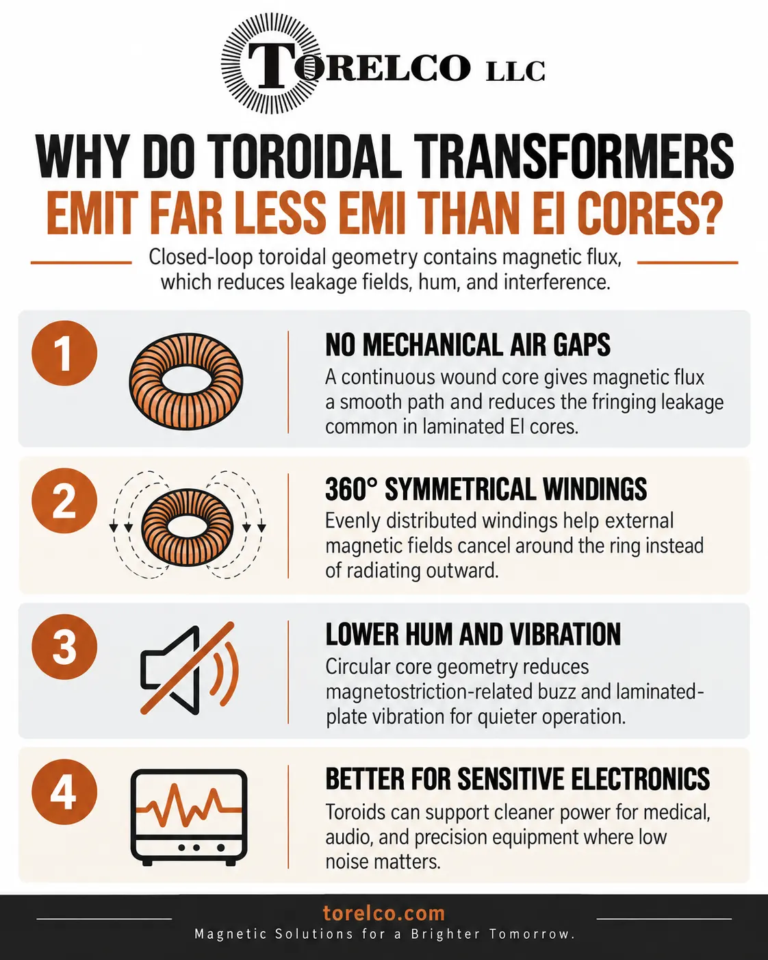
- Zero Mechanical Air Gaps: Because the core ribbon is wound continuously without butt joints or mating seams, magnetic flux travels through a homogeneous, uniform path with zero fringing leakage.
- 360-Degree Symmetrical Windings: Primary and secondary copper wire turns are distributed evenly around the entire circumference of the doughnut ring. The magnetic fields generated by opposite sides of the ring naturally cancel each other in the far field.
- Grain-Oriented Magnetic Alignment: The continuous steel strip is magnetized along its natural rolling grain direction across the entire 360-degree loop, maximizing magnetic permeability and containing over 90% to 95% of magnetic flux lines within the core interior.
Comparing Toroidal and E-I Lamination Core Architectures
Performance Dimension | Toroidal Core Transformer | Standard Laminated E-I Core Transformer |
Radiated Stray Magnetic Field | Extremely Low (1/8th to 1/10th of EI core) | High; radiates strong 60 Hz dipole field |
Acoustic Mechanical Hum | Virtually silent (<30 dBA at rated load) | Audible buzz (40 to 55 dBA) from loose laminations |
Core Air Gaps | Zero; 100% continuous wound steel tape | Multiple mechanical butt joints between E & I plates |
Power Conversion Efficiency | High (90% to 95% typical efficiency) | Moderate (75% to 85% typical efficiency) |
Physical Volume and Weight | Approximately 50% lighter and smaller for same VA | Bulky, heavy rectangular footprint |
Winding Distribution | Uniform 360° distribution over core surface | Concentrated on central bobbin leg |
Inrush Current Profile | High initial inrush due to low winding resistance | Moderate inrush cushioned by core air gaps |
Acoustic Noise and Mechanical Magnetostriction
Electromagnetic emissions are not the only form of pollution transformers produce. In audio recording gear, hospital patient monitors, and laboratory spectrometers, audible mechanical hum is equally unacceptable. In an EI transformer, two physical mechanisms produce acoustic noise.
First, magnetic attraction between the individual laminated plates causes them to vibrate against one another at twice the line frequency (120 Hz). Second, the physical phenomenon of magnetostriction causes the iron crystals to expand and contract slightly during each alternating magnetic cycle. In an EI core, the uneven flux distribution excites these vibrations into an audible buzz.
In a toroidal transformer, the steel tape is wound under precise mechanical tension, spot-welded, and impregnated with thermosetting epoxy resin. The symmetrical circular geometry distributes magnetic forces uniformly in all directions, canceling mechanical stress points. As a result, toroidal transformers operate virtually inaudibly, maintaining noise levels below 30 dBA even when driven near maximum rated load capacity.
Inrush Current Management and Circuit Protection
While toroidal transformers deliver outstanding magnetic containment and high electrical efficiency, their electrical properties require thoughtful power supply design. Because toroidal cores have no air gaps, they exhibit high magnetic remanence—meaning they retain residual magnetic flux when powered off. Furthermore, because primary copper windings are shorter and more compact than bobbin-wound coils, primary DC winding resistance is exceptionally low.
When a toroidal power supply is switched on at the peak of the AC voltage waveform, or when residual core magnetism aligns with the incoming half-cycle, the core can briefly saturate for a few milliseconds, drawing an initial inrush current 10 to 40 times higher than steady-state operating current. Power design engineers easily address this behavior by incorporating time-delay (slow-blow) fuses, negative temperature coefficient (NTC) thermistors, or active triac/relay soft-start circuits.
Electrostatic Shielding for Critical Medical and Audio Isolation
For mission-critical applications governed by IEC 60601-1 medical safety standards or ultra-low-noise professional audio specifications, custom toroidal transformers can include a specialized electrostatic Faraday shield. A thin, insulated copper foil is wound between the primary and secondary winding layers, with a dedicated ground lead brought out to chassis earth.
This grounded electrostatic barrier intercepts capacitive common-mode noise traveling across the AC mains before it can couple electrostatically into the secondary circuits. Combined with external silicon steel flux bands (G-metal shielding), custom toroids achieve absolute electromagnetic silence, protecting sensitive patient physiological monitors and studio recording channels from line spikes and RF garbage.
Specifying Custom Toroidal Magnetics for Demanding Hardware
Selecting power conversion magnetics requires balancing tight space constraints, thermal dissipation budgets, and stringent electromagnetic compatibility targets. For engineering teams developing high-density electronics, replacing noisy laminated transformers with custom-engineered toroidal transformers is the most reliable way to eliminate stray magnetic hum at the source.
By collaborating with experienced magnetics specialists who understand core geometry, custom winding patterns, and electrostatic shielding techniques, hardware designers ensure their products pass FCC Class B and CISPR emissions standards with generous operating margins. Investing in optimized toroidal power conversion delivers quiet, efficient, and dependable power across the entire operating lifespan of advanced electronic equipment.